Legendary Service. Since 1974.SM
Your Crutchfield WireGuide™
Wiring can be tricky, so we created this custom diagram to simplify your installation. Review it before you begin, and reach out to our Virginia‑based tech support team if you need help.
Your vehicle:
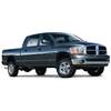
2006 Dodge Ram 2500
with 7 Speakers; without Navigation system
Your stereo:

Kenwood Excelon Reference DMX1057XR
Your adapter(s):
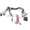
iDatalink HRN-RR-CH2 Interface Harness
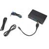
iDatalink Maestro RR Interface Module
Preparation
iDatalink HRN-RR-CH2 Interface Harness Notes
iDatalink Maestro RR Interface Module Notes
Wiring connections
-
1. Make these connections
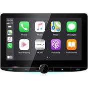
Kenwood Excelon Reference DMX1057XR
Black 22-Pin Connector
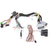
iDatalink HRN-RR-CH2 Interface Harness
ADS-HRN(SR)-CHR02 Harness
Yellow
Battery
Pin 12
Yellow
12V (+)
Pin
Orange/White
Dimmer Control
Pin 13
Orange
Illumination (+)
Pin
Black
Ground
Pin 1
Black
Ground
Pin
Red
Ignition
Pin 2
Red
Accessory (+)
Pin
Light Green
Parking Sensor
Pin 17
Light Green
E-Brake
Pin
Blue/White
Power Control
Pin 3
Blue/White
Amp Turn-On
Pin
Violet/White
Reverse Gear
Pin 18
Violet/White
Reverse Light (+)
Pin
Your receiver's reverse wire only needs to be connected if you will be using a backup camera.
Pink
Speed Sense
Pin 5
Pink
Vehicle Speed
Pin
White/Black
To Front Left Speaker
Pin 10
White/Black
LF Speaker (-)
Pin
White
To Front Left Speaker
Pin 11
White
LF Speaker (+)
Pin
Gray/Black
To Front Right Speaker
Pin 9
Gray/Black
RF Speaker (-)
Pin
Gray
To Front Right Speaker
Pin 8
Gray
RF Speaker (+)
Pin
Green/Black
To Rear Left Speaker
Pin 21
Green/Black
LR Speaker (-)
Pin
Green
To Rear Left Speaker
Pin 22
Green
LR Speaker (+)
Pin
Violet/Black
To Rear Right Speaker
Pin 20
Violet/Black
RR Speaker (-)
Pin
Violet
To Rear Right Speaker
Pin 19
Violet
RR Speaker (+)
Pin
-
2. Kenwood Excelon Reference DMX1057XR
Green/Red
CAM+
Pin 6
Green/White
CAM-
Pin 7
Yellow RCA
Camera Input
Pin C
-
3. iDatalink HRN-RR-CH2 Interface Harness
Red/Brown
OBDII Connection
Pin
Yellow/Brown
OBDII Connection
Pin
Unused wires
| Black 22-Pin Connector |
|---|
| Blue Antenna Control Pin 4 |
| Blue/Yellow Steering remote control Pin 16 |
| ADS-HRN(SR)-CHR02 Harness |
|---|
| Yellow/Black Foot Brake Pin |
| Brown Not Connected Pin The brown wire may not be present on your harness. |
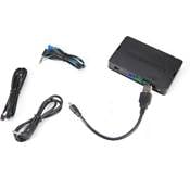 Blue 4-Pin SWC Connector |
|---|
| 3.5mm Jack Steering Wheel Control Cable Pin |
| Blue/Yellow Steering Wheel Control Cable Pin This wire may be terminated by a purple connector. If present, you may need to cut off the purple connector in order to connect this wire to your radio's steering wheel control wire. |
The information contained in this document, is presented as a convenience and is without warranties or guarantees of any type. Due to the constantly changing nature of this type of information and running changes in vehicle production this information may not be timely and/or accurate. Any person or entity using this information does so at his or her own risk. If you find this information is different from your vehicle, please stop working immediately and call our Tech Support team for help.
